Product Overview
NOTE: Fixed Shipping Rate not available in Hawaii or Alaska.
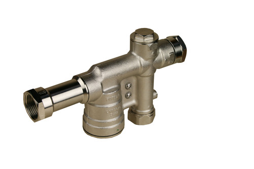
Motorized 3-way backup valve to select between primary and secondary water sources, allowing only one at a time.
Rainwater collection systems can be designed to provide uninterrupted supply of water by implementing a backup method from a second source.
The most reliable backup method is 'direct backup' in which both the backup source (typically municipal supply or well water) and rainwater supply directly connect to the plumbing system through a motorized three-port valve. When there is sufficient water in the rainwater tank, the valve connects the rainwater supply to the plumbing system. When the water level in the rainwater tank reaches a pre-set low level, the valve connects the backup water supply to the plumbing system. A reduced pressure backflow preventer is used between the backup supply and the valve to assure there is no cross-contamination.
Our unique three-port valve is ideal for rainwater systems. The hydraulic section of the valve is optimized for low pressure drop and consists of a nickel-plated brass valve body with a stainless-steel ball and teflon seats. When power is applied, the ball rotates 90°. When the water level returns to the desired level, return state voltage applied to the opposite terminal returns the valve to its normal state. For cistern backup systems, the solenoid valve is controlled by a float switch or by our Rainwater System Controller in which case the return state voltage must be applied by means of the auto-charging battery backup option or an optional external relay which we can provide at an additional cost.
Features include: manual override (black knob on top) for use in the event of loss of electrical power. The unit also features an internal 4W thermostatic anti-condensation heater to alleviate condensation when the temperature inside the housing drops below 77°F.
Options:
An internal battery backup option is available which provides an alternative power supply to drive the actuator to a pre-set failsafe position in the event of a power failure.
Method of Operation:
On receipt of a continuous power signal within the voltage range shown above, the motor runs and, via a flat gear system, rotates the output shaft. The motor is stopped by internal cams striking micro switches. On receipt of a reversing continuous signal, the motor turns in the opposite direction reversing the output drive.
Note:
The power signal needs to remain on at all times to activate the thermostatic anti-condensation heater. The volt free end of travel confirmation switches must NOT be used to cut the power.
|
| Specifications: | |||||||||
| Water Lines: | 3 X 1" | ||||||||
|
|
||||||||
| Working Time: | 8 Seconds / 90° | ||||||||
| Torque Limiter: | STD | ||||||||
| Max Pressure: | 400 PSI | ||||||||
| Duty Rating: | 75% | ||||||||
| Protection: | IP65-67 | ||||||||
| Manual Intervention: | STD | ||||||||
| Position Indicator: | STD | ||||||||
| Working Temp: | -4 to +131°F | ||||||||
| Heater: | Automatic below 77°F | ||||||||
| Aux. Limit Switches: |
STD (2) |
||||||||
|
Electric Actuator Power Consumption |
||
| High Voltage | Nominal Voltage | 100 - 240 VAC |
| Absorbed Current | 0.2 - 0.3A | |
| Absorbed Power | 30 - 48VA | |
| Low Voltage | Nominal Voltage |
24V AC/DC |
| Absorbed Current |
1.0A |
|
| Absorbed Power | 24VA | |
| All | Frequency | 50/60Hz |
|
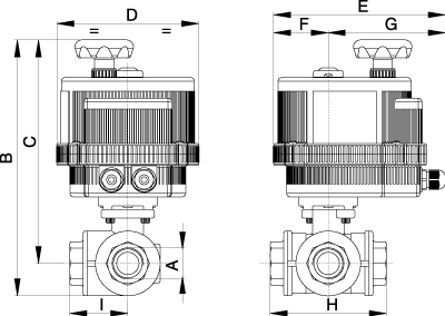
Dimensions (in.) |
|||
| A | 1" | 1-1/4" |  |
|
B |
9.98 | 10.43 | |
| C | 9.03 | 9.25 | |
| D | 6.18 | 6.18 | |
| E | 7.5 | 7.5 | |
| F | 2.38 | 2.38 | |
| G | 5.12 | 5.12 | |
| H | 3.74 | 4.39 | |
| I | 1.87 | 2.20 | |
|
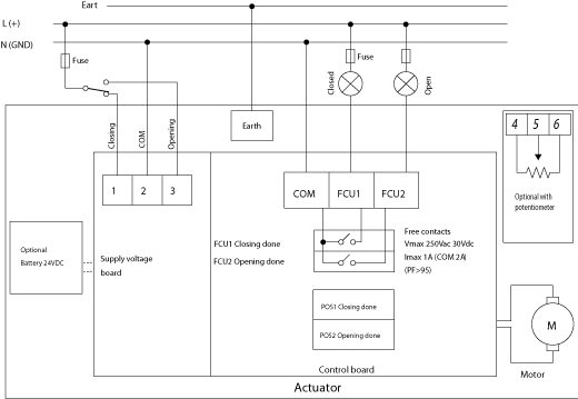
Wiring Diagram |
 |


