null

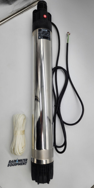
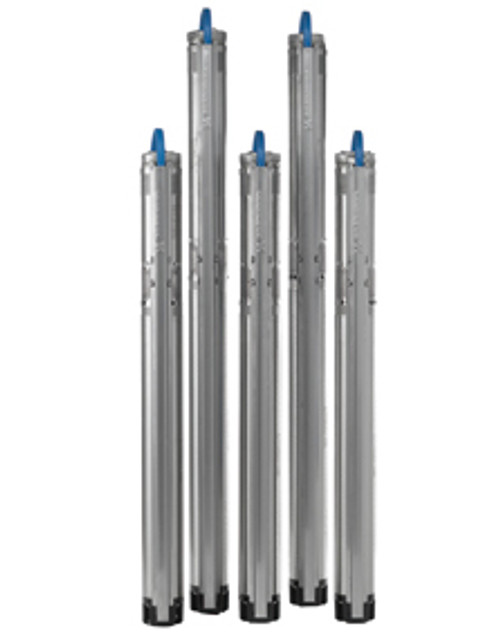
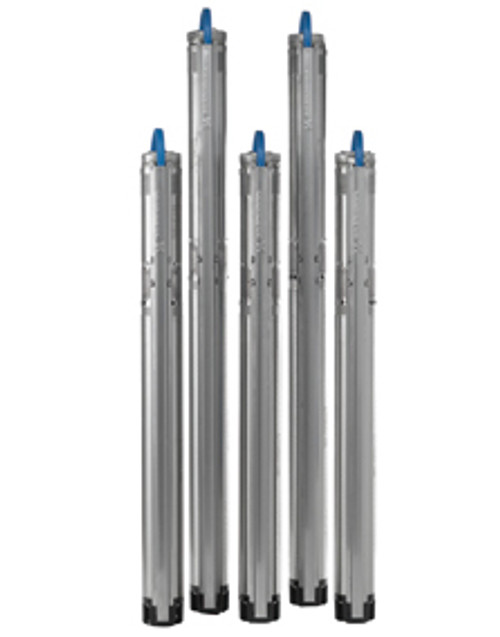
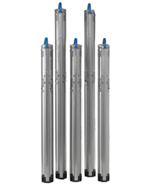
BHP 1000 - 4" Submersible Transfer Pump (115/230V)

$439.95
SKU:
60201433-G
Weight:
28.70 LBS
Shipping:
Calculated at Checkout
Adding to cart… The item has been added

Product Overview

BHP 4” submersible pumps

4” multi-impeller submersible pumps designed for pressurization, gardening and irrigation, withdraw water from underground in domestic and residential, civil and commercial areas and irrigation systems also in agriculture.

CONSTRUCTION FEATURES OF THE PUMP
Technopolymer impellers housed in the stage box with stainless steel shim rings. Integrated suction filter. Built-in check valve in technopolymer.

CONSTRUCTION FEATURES OF THE MOTOR
Integrated thermal protection and capacitor.

TECHNICAL DATA
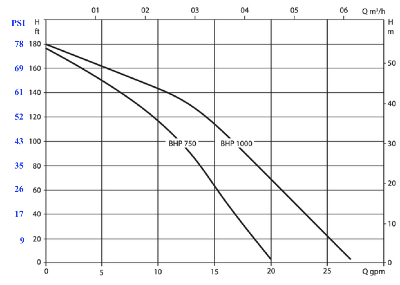
Flow rate: up to 27 GPM
Head up to: 180 feet
Maximum immersion depth : 49 feet
Type of pumped liquid: Clean, free of solids and abrasive substances, non-viscous, non-aggressive, non-crystallized and chemically neutral
Liquid temperature: From +32°F to +104°F
Maximum operating pressure: 116 psi (8 bar)
Pump maximum diameter: 3.9”
Single phase power input: 1x115v 60Hz
Power cable: 10 Feet
Possible type of installation: Fixed in vertical position

Certification: CAN/CSA C22.2 No. 108-14 - Liquid Pumps
UL 778- 6th Ed. - Motor Operated Water Pumps


PERFORMANCE CURVE

dab-bhp-1000-750-curves


Documentation:

Technical Specs

Quick Start Guide

How to Wire a 115V Float Switch to a Submersible BHP-1000 Pump

Submersible pumps (not considered to be "on-demand" pumps) use float switches instead of pressure changes to perform automatic operation. The float switch moves with the water level in the tank and determines when the pump turns on and off. Below are the instructions for wiring a float switch to a 115V submersible pump so it will operate automatically as needed.

Please note: The information below refers to 115V pumps and wiring. We recommend using a piggy-back float switch or control panel to operate 230V pumps. DO NOT USE THE METHOD DESCRIBED BELOW FOR 230V PUMPS.

In 115V wiring, there are 3 wire legs:

1) Hot 

2) Neutral   

3) Ground.

The pump will have these 3 wires and the incoming power supply will have these 3 wires:

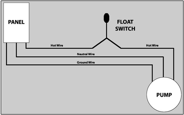
-The neutral (white) wire from the panel will connect directly to the neutral (white) wire from the pump.

-The ground (green) wire from the panel will connect directly to the ground (green) wire from the pump.

This leaves the hot wire from the panel (or 115V Outlet) and the hot wire from the pump.

The float switch has two legs. One leg of the float switch will connect to the hot wire from the panel or 115V receptacle/outlet, and the other leg will connect to the hot wire from the pump. 

Please note:

Most float switches have a white and black wire, which means you will most likely have a white wire to black wire connection. This is normal. Once these connections are made, you may turn the power on, and the submersible pump should operate according to the position of the float switch. Pump up, normally closed float switches, when used in this manner, turn the pump off when the float is in the up position and turn the pump on when the float is in the down position.

Pump down, normally open float switches, when used in this manner, turn the pump on when the float is in the up position and turn the pump off when the float is in the down position.

Wiring Diagram

 floatswitchwiring.jpeg


Warranty Information

2 year manufacturer